ROS联合Webots之实现趣味机器人巡线刷圈
ROS联合Webots实现机器人视觉巡线刷圈
注意:
- 再学习本系列教程时,应该已经安装过ROS了并且需要有一些ROS的基本知识
ubuntu版本:20.04
webots版本:2021a
ros版本:noetic
前言
最近看到Youtube上大部分博主都在做巡线,笔者也来凑凑热闹。
此项目基于tianbot_mini机器人完成。
项目开源地址:tianbot_mini_webots
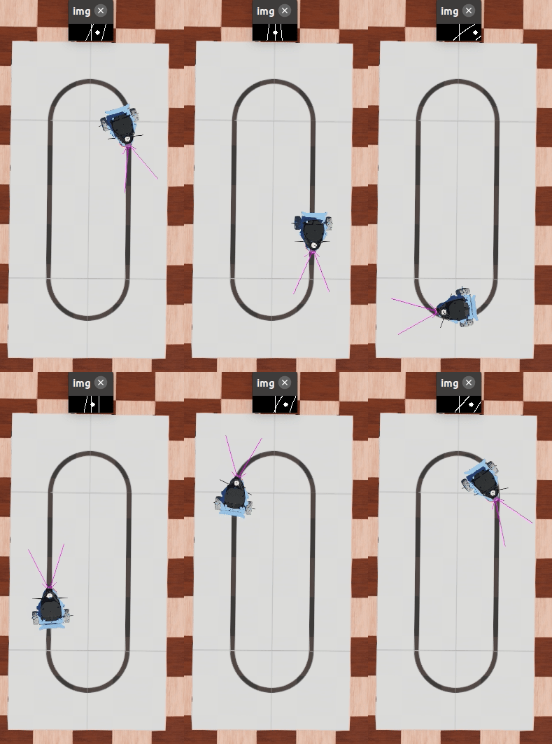
效果
小车已经设置为最高速度10

ROS控制方案
- 在功能包中添加opencv库
- 因为机器人要行使,所以首先要使能电机
- 要用到camera,所以使能camera
- 调整camera的前瞻角度
- 写opencv检测算法
- 更具PID控制算法控制两个轮子的速度
1. 配置功能包
1.1 配置CMakeLists.txt
自己找到相应位置添加
set(CMAKE_CXX_FLAGS "-std=c++11") # 调用OpenCV配置:C++版本为11

find_package(OpenCV 4.2 REQUIRED) # 找OpenCV 4.2 安装路径

include_directories(
  ${OpenCV_INCLUDE_DIRS} # 加载OpenCV 4.2 安装路径
)

add_executable(tianbot_line_follow src/tianbot_line_follow.cpp)
add_dependencies(tianbot_line_follow webots_ros_generate_messages_cpp)
target_link_libraries(tianbot_line_follow	${catkin_LIBRARIES})
target_link_libraries(tianbot_line_follow	${OpenCV_LIBS}) # 使用到Opencv库需要通过Opencv链接库
2. 使能电机
笔者这边写了tianbot_velocity.cpp来使能左右电机,其主要代码如下所示:
// 初始化电机
for (int i = 0; i < NMOTORS; ++i) {
    // 速度控制时position设置为缺省值INFINITY(必须要这一步,否则webots会报错)
    set_position_client = n->serviceClient<webots_ros::set_float>(string("/tianbot_mini/") + string(motorNames[i]) + string("/set_position"));
    set_position_srv.request.value = INFINITY;
    if (set_position_client.call(set_position_srv) && set_position_srv.response.success)
        ROS_INFO("Position set to INFINITY for motor %s.", motorNames[i]);
    else
        ROS_ERROR("Failed to call service set_position on motor %s.", motorNames[i]);
    // velocity初始速度设置为0
    set_velocity_client = n->serviceClient<webots_ros::set_float>(string("/tianbot_mini/") + string(motorNames[i]) + string("/set_velocity"));
    set_velocity_srv.request.value = 0.0;
    if (set_velocity_client.call(set_velocity_srv) && set_velocity_srv.response.success == 1)
        ROS_INFO("Velocity set to 0.0 for motor %s.", motorNames[i]);
    else
        ROS_ERROR("Failed to call service set_velocity on motor %s.", motorNames[i]);
}
3. 使能camera
创建一个机器人巡线主程序tianbot_line_follow.cpp,使能camera主要代码如下:
// 使能摄像头
ros::ServiceClient set_camera_client;
webots_ros::set_int camera_srv;
ros::Subscriber sub_camera_img;

set_camera_client = n->serviceClient<webots_ros::set_int>(string(ROBOT_NAME)+string("camera/enable"));
camera_srv.request.value = TIME_STEP;
// 此代码等同于rosservice call /tianbot_mini/camera/enable 32
if (set_camera_client.call(camera_srv) && camera_srv.response.success) {
    // 使能成功立即订阅camera发布的topic
    sub_camera_img = n->subscribe(string(ROBOT_NAME)+string("camera/image"), 1, CameraCallback);
    ROS_INFO("Camera enabled.");
} else {
    if (!camera_srv.response.success)
    ROS_ERROR("Failed to enable Camera.");
    return 1;
}
4. 调整camera
-
首先在Robot机器人主节点下的children下添加camera节点
-
给camera节点配置shape为Box,size设置为(0.02 0.009 0.01)
-
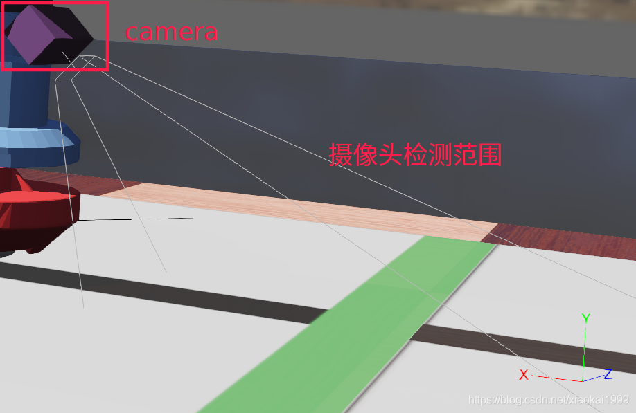
使用ctrl+F9显示摄像头检测范围,如下图所示

-
有了显示摄像头的检测范围,就能很快速的调整camera的前瞻角度,这个更具自己算法作相应的调整,笔者这边的角度参数为(0.357 -0.357 -0.863)
4.1 opencv获取图像
上面的使能操作中已经订阅了camera发布的图像topic,接下来只需要写camera回调函数来获取图像数。
#include <opencv2/opencv.hpp>
using namespace cv;                             // opencv
void CameraCallback(const sensor_msgs::Image::ConstPtr &value){
    // 将webots提供的uchar格式数据转换成Mat
    Mat img_rgb = Mat(value->data).clone().reshape(4, 64);
    Mat img;
    img = ImageProcessFun(img_rgb);
    FindPoints(img);
}
5. opencv检测算法
之前笔者写过一篇基于v-rep仿真软件的视觉寻线算法,想了解的同学可以移步至:
疫情让我使用V-rep仿真(结合pythonAPI)实现机器人视觉巡线+pid调速
这次的算法相比较于上次的算法更简单,适用于这种简单的巡线场景。
5.1 算法解析
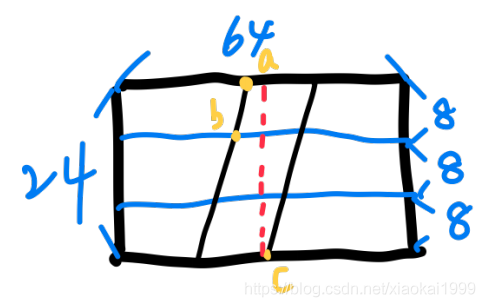
将获取到的(6464)大小的图像,截取底部(2464)大小的区域用于识别,减少识别面积,提高运算速度。
将图像再按3快均匀划分,分为前,中,后三块,如下图所示:

设置左点X,右点Y,中点M。X从左往右检测,Y从右往左检测,M则为X点和Y点的中点。
首先检测前块左边线的点,称为左点a,如果存在X=a
否则检测中块左边线的点,成为左点b,如果存在X=b
如果都不存在,则检测后块左边线的点,同上。找到了X就要找Y,直接从右往左检测后块右边线点c,如果存在Y=c。
否则判断为偏离路径。
M = (X+Y)/2
M(f,g)和中心线计算行里的偏移距离,将此值带入PID求出两轮的速度。
5.2 图像处理
首先想要计算,必须经过一系列的图像处理,让图像更方便的进行计算。
void ImageProcessFun(Mat img_rgb){
    img_rgb(Range(40, 64),Range(0, 64)).copyTo(img_gray);   //选择感兴趣区域
    cvtColor(img_gray, img_gray, COLOR_BGR2GRAY);           // 将图像转换为灰度图像
    threshold(img_gray, img, 100, 255, THRESH_BINARY);      // 对感兴趣区域进行二值化操作
    Canny(img, img, 20, 40);                                // 由于仿真没有额外复杂环境,使用Canny边缘检测

}
最后效果如下所示:

[原图]

[处理后的图]
5.3 找出关键点
void FindPoints(Mat img){
    Point left_point, right_point, middle_point;// 左上一点,右下一点,求出中点
    int flag = 1;// 点数
    // 找出左边线
    while (flag <= 4){
        for (int i = 0; i < 64; i++){
            // 在前块中查找左边线的点
            if (flag == 1){
                if((int)img.at<uchar>(0, i) == 255){
                    left_point.x = i;
                    left_point.y = 0;
                    cout<<"left_point="<<left_point<<endl;
                    flag = 4;
                    break;
                }
            }
            // 在中快中查找左边线的点
            else if (flag == 2){
                if((int)img.at<uchar>(9, i) == 255){
                    left_point.x = i;
                    left_point.y = 9;
                    cout<<"left_point="<<left_point<<endl;
                    flag = 4;
                    break;
                }
            }
            else{
                cout<<"已超出范围"<<endl;
                flag = 6;
                break;
            }
        }
        flag++;
    }
    // 找到左边线后求解右边线
    for (int i = 63; i >= 0; i--){
        if((int)img.at<uchar>(23, i) == 255){
            right_point.x = i;
            right_point.y = 23;
            cout<<"right_point="<<right_point<<endl;
            break;
        }
    }

    //计算出中间点
    middle_point.x = left_point.x + (right_point.x - left_point.x)/2;
    middle_point.y = 12;// 固定行高
    cout<<"middle_point="<<middle_point<<endl;
    line(img, Point(32,0), Point(32,24), Scalar(255));// 在感兴趣区域中绘制中心线
    line(img, middle_point, middle_point, Scalar(255),5);// 画出中心点
}
6. PID输出速度
使用位置式PID,网上都有教程,自行查找。
struct pid
{
    float pid_setValue;     // 设置值
    float pid_actualValue;  // 当前值
    float Kp;
    float Ki;
    float Kd;
    float err;              // 偏差
    float last_err;         // 上一次的偏差
    float speed;
    float T;                // 更新周期
    float integral;         // 累积误差
}_pid;
void pid_init(float Kp,float Ki,float Kd){
    _pid.pid_setValue = 0.0;
    _pid.pid_actualValue = 0.0;
    _pid.Kp = Kp;
    _pid.Ki = Ki;
    _pid.Kd = Kd;
    _pid.err = 0.0;
    _pid.last_err = 0.0;
    _pid.speed = 0.0;
    _pid.T = .0 ;
    _pid.integral = 0.0;
}

float pid_run(float value){
    _pid.pid_setValue = value;
    _pid.err = _pid.pid_setValue - _pid.pid_actualValue;
    _pid.integral = _pid.integral + _pid.err;
    _pid.speed = _pid.err * _pid.Kp + _pid.integral *_pid.T * _pid.Ki + (_pid.err - _pid.last_err) * _pid.Kd;
    _pid.last_err = _pid.err;
    _pid.pid_actualValue = _pid.speed;

    return _pid.pid_actualValue;
}

pid_run((float)(middle_point.x - 32))/2.0;// 输入差值,输出左右轮的速度差
7. 速度更新
void updateSpeed(Point middle_point) {
    double speed_diff=0.0;// 定义速度差变量
    speed_diff = pid_run((float)(middle_point.x - 32))/2.0;// 计算速度差
    cout<<"speed_diff="<<speed_diff<<endl;
    speeds[0] = speed_diff;
    speeds[1] = -speed_diff;

    // 确定基准速度(10为最大)
    if (abs(middle_point.x - 32) <= 2){
        cspeed=9.0;// 直行速度为9
    }else if (abs(middle_point.x - 32) > 2){
        cspeed=7.0;// 弯道速度为7
    }

    cout<<"leftspeed="<<speeds[0]<<endl;
    cout<<"rightspeed="<<speeds[1]<<endl;
    for (int i = 0; i < NMOTORS; ++i) {
        // 发送给webots更新机器人速度
        set_velocity_client = n->serviceClient<webots_ros::set_float>(string("/tianbot_mini/") + string(motorNames[i]) + string("/set_velocity"));
        set_velocity_srv.request.value = speeds[i]+cspeed;// 速度差+基准速度
        set_velocity_client.call(set_velocity_srv);
    }
}
结语
本文也是基于笔者的学习和使用经验总结的,主观性较强,如果有哪些不对的地方或者不明白的地方,欢迎评论区留言交流~
为了能和读者进一步讨论问题,建立了一个微信群,方便给大家解答问题,也可以一起讨论问题。
加群链接
✌Bye