NXP-无感BLDC代码MCSPTE1AK116_BLDC_6Step代码详解
目录
FTM1_Ovf_Reload_IRQHandler()重点
对MCSPTE1AK116_BLDC_6Step工程代码进行理解
开发平台
开发平台S32DS for ARM V2.2
文章可以配合无感BLDC对应技术文档使用
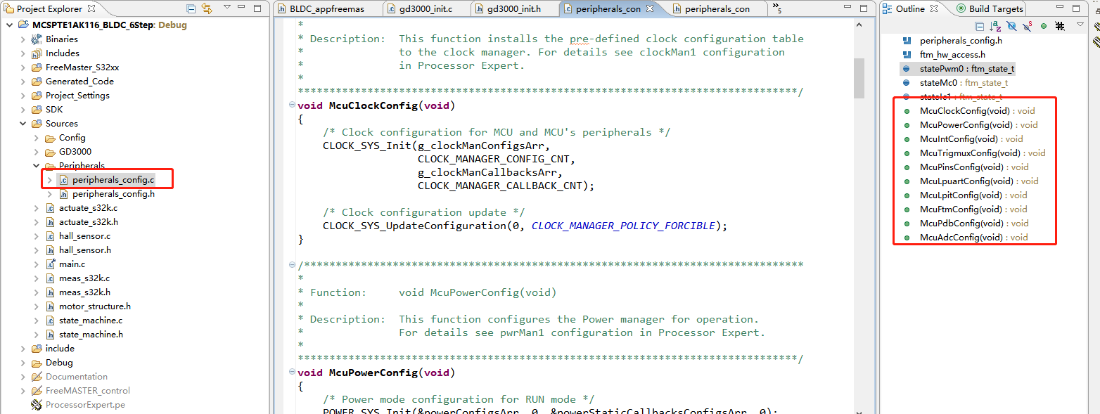
工程目录
重点关注红色框圈出来的部分

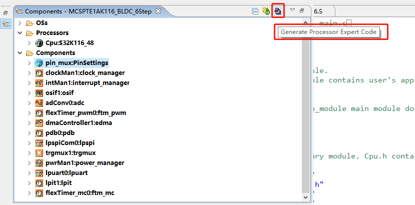
Generated_Code
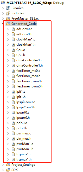
这个文件夹下的文件是你配置完CPU基本外设模块后自动生成的代码
比如在pin_mux.c下,则是你配置的各种GPIO
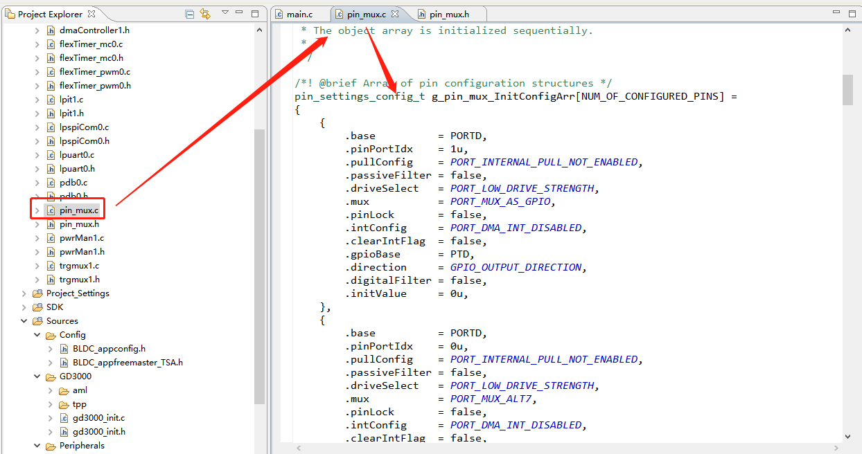
其它各模块类似。
Sources
Sources目录下则是我们需要的电控应用层文件
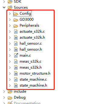
Config
Config下有两个头文件

其中BLDC_appconfig.h文件中有:
电机的参数
//Motor Parameters
//----------------------------------------------------------------------
//Pole-pair number = 2 [-]
//Back-EMF constant = 0.005872 [V.sec/rad]
//Phase current nominal FRAC16(0.240000000000)
//Phase voltage nominal FRAC16(0.266666666667)
//----------------------------------------------------------------------
//Application scales
#define I_MAX (25.0)//最大电流
#define U_DCB_MAX (45.0)//最大总线电压
#define N_MAX (5000.0)//最大转速
#define I_DCB_OVERCURRENT FRAC16(0.200000000000)//总线电流过流?
#define U_DCB_UNDERVOLTAGE FRAC16(0.200000000000)//总线电压欠压
#define U_DCB_OVERVOLTAGE FRAC16(0.400000000000)//总线电压过压
#define I_DCB_LIMIT FRAC16(0.120000000000)//总线电流限制?
#define U_DCB_TRIP FRAC16(0.555555555556)//?
#define N_NOM FRAC16(0.900000000000)//一般转速
#define I_PH_NOM FRAC16(0.240000000000)//一般相电压
#define U_PH_NOM FRAC16(0.266666666667)//一般相电流
//Mechanical Alignment 预定位
#define ALIGN_VOLTAGE FRAC16(0.166666666667)//预定位时的电压
#define ALIGN_DURATION (20000)//预定位时间
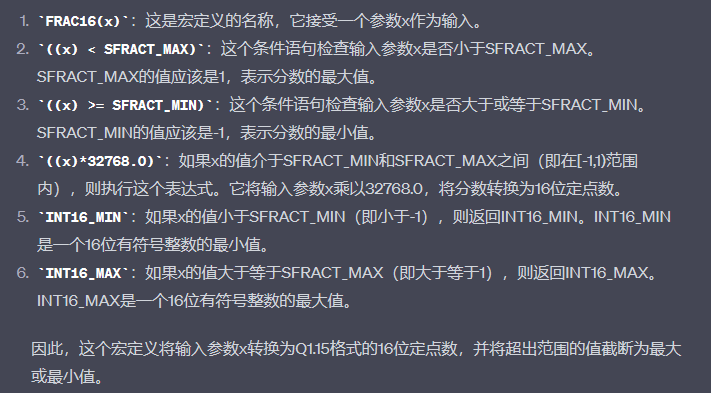
其中FRAC16(),是一个数学公式宏定义
/** Macro converting a signed fractional [-1,1) number into a 16-bit fixed point number in format Q1.15.*/
#define FRAC16(x) ((tFrac16) (((x) < SFRACT_MAX) ? (((x) >= SFRACT_MIN) ? ((x)*32768.0) : INT16_MIN) : INT16_MAX))把一个范围在[-1,1)内的有符号分数转换为格式为Q1.15的16位定点数。
BLDC参数
速度环、扭矩环的KpKi值、速度斜坡
//BLDC Control Loop
//----------------------------------------------------------------------
//Loop sample time                      = 0.001 [sec]
//----------------------------------------------------------------------
//Control loop limits
#define CTRL_LOOP_LIM_HIGH              FRAC16(0.900000000000)
#define CTRL_LOOP_LIM_LOW               FRAC16(0.100000000000)

//Speed Controller - Parallel type  速度控制
#define SPEED_LOOP_KP_GAIN              FRAC16(0.857864233940)
#define SPEED_LOOP_KP_SHIFT             (-10)
#define SPEED_LOOP_KI_GAIN              FRAC16(0.643398175455)
#define SPEED_LOOP_KI_SHIFT             (-9)

//Speed ramp increments   速度斜坡            上升 下降
#define SPEED_LOOP_RAMP_UP              FRAC32(0.000400000000)
#define SPEED_LOOP_RAMP_DOWN            FRAC32(0.000400000000)

//Torque Controller - Parallel type  扭矩控制
#define TORQUE_LOOP_KP_GAIN             FRAC16(0.888888888889)
#define TORQUE_LOOP_KP_SHIFT            (-5)
#define TORQUE_LOOP_KI_GAIN             FRAC16(0.533333333333)
#define TORQUE_LOOP_KI_SHIFT            (-6)
#define TORQUE_LOOP_MAF                 (0.03125)
无感模式下的一些参数
//Sensorless Control Module
//----------------------------------------------------------------------
//Timer Frequency                       = 750000 [Hz]
//----------------------------------------------------------------------
#define N_MIN                           FRAC16(0.160000000000)
#define N_START_TRH                     FRAC16(0.160000000000)
#define STARTUP_CMT_CNT                 (10)//启动阶段换相次数
#define STARTUP_CMT_PER                 (15000)//启动阶段控制换相周期
#define CMT_T_OFF                       FRAC16(0.200000000000)
#define FREEWHEEL_T_LONG                (100)
#define FREEWHEEL_T_SHORT               (50)
#define SPEED_SCALE_CONST               (4500)
#define CMT_PER_MIN                     (750)
#define START_CMT_ACCELER               FRAC16(0.878763934440)//启动阶段电机加速度
#define INTEG_TRH
Config下的另一个文件则是与freemaster相关的配置,可暂时不看。
Peripherals
Peripherals文件下则是一些外设的基本配置
说白了就是提供API接口函数,以供应用层方便直接调用Generated_Code生成的底层驱动代码。
FTM/PDB/ADC配置参数
FTM0 PWM 在其头文件中,有定义PWM周期20KHz,也就式50us
根据公式
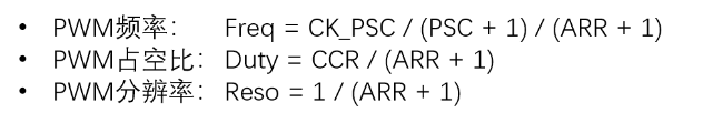
也就是20K = 48M / 1 /2400
ARR+1 = 2400
PWM 周期50us 被分成2400份,所以一般PWM周期就是CCR = 1200
// FTM0 PWM period in ticks 20kHz/50us @48MHz system clock
#define PWM_MODULO      	 		2400	// PWM period
#define HALF_PWM_MODULO      	 	1200	// Full PWM period
#define PWM_CHANNEL_GROUP			0xcf	//PWM channel 0 - 1; 2 - 3; 6 - 7;
FTM1 clock则定义成一般定时器,每1ms进行一次中断。
// 1ms timeout @750kHz FTM1 clock
#define FTM1_PERIOD_1MS     		749
#define FTM1_UPDATE_MOD(modulo) 	(FTM1->SC) &= ~FTM_SC_CLKS_MASK; \
									(FTM1->MOD) = modulo; \
									(FTM1->SC) |= FTM_SC_CLKS(1u)
PDB最小延迟时间
#define PDB_DELAY_MIN 100 // Lower limit to avoid PDB sequence errorADC通道
#define ADC1_DCBI    				3	// DC bus current
#define ADC1_DCBV    				12	// DC bus voltage
#define ADC0_BEMFA   				9	// Phase A voltage
#define ADC0_BEMFB   				14	// Phase B voltage
#define ADC0_BEMFC   				13	// Phase C voltage
actuate_s32k
主要是对PWM六步换相控制、使能的一些结构体与函数。
六步换相顺时针、逆时针编码,简单理解就是控制在不同扇区下,哪一相PWM,哪一相接地,哪一相不接。
/* FTM0 channel output mask control */
const uint8_t ui8FTM0OutmaskVal[2][8] =
{
    /* Clockwise rotation direction 顺时针方向*/
    {
        0xc4,   /* sector 0 */
        0x4C,   /* sector 1 */
        0x43,   /* sector 2 */
        0xc1,   /* sector 3 */
        0x0D,   /* sector 4 */
        0x07,   /* sector 5 */
        0x05,   /* alignment vector */
        0xcF    /* PWM off */
    },
    /* Counterclockwise rotation direction 逆时针方向*/
    {
        0xc1,   /* sector 3 */
        0x43,   /* sector 2 */
        0x4c,   /* sector 1 */
        0xc4,   /* sector 0 */
        0x07,   /* sector 5 */
        0x0D,   /* sector 4 */
        0x05,   /* alignment vector */
        0xcF    /* PWM off */
    }
};


/* FTM0 channel software output control */
const uint16_t ui16FTM0SwOctrlVal[2][8] =
{
    /* Clockwise rotation direction */
    {
        0x0808, /* sector 0 */
        0x8080, /* sector 1 */
        0x8080, /* sector 2 */
        0x0202, /* sector 3 */
        0x0202, /* sector 4 */
        0x0808, /* sector 5 */
        0x0A0A, /* alignment vector */
        0x0000  /* PWM off */
    },
    /* Counterclockwise rotation direction */
    {
        0x0202, /* sector 3 */
        0x8080, /* sector 2 */
        0x8080, /* sector 1 */
        0x0808, /* sector 0 */
        0x0808, /* sector 5 */
        0x0202, /* sector 4 */
        0x0A0A, /* alignment vector */
        0x0000  /* PWM off */
    }
};
使能PWM输出函数,这是占空比为0
tBool ACTUATE_EnableOutput(tBool ftmInputTrig)
{
    uint16_t duty_cycle;

    /* Enable FTM0 PWM */
    FTM_DRV_MaskOutputChannels(INST_FLEXTIMER_PWM0, 0x0, false);

    /* Apply 0% duty cycle */
    duty_cycle = 0;

    /* Update duty cycle */
    ACTUATE_SetDutycycle(duty_cycle, ftmInputTrig);

    return 1;
}
禁止PWM函数
tBool ACTUATE_DisableOutput(tBool ftmInputTrig)
{
    uint16_t duty_cycle;

    /* Disable FTM0 PWM */
    FTM_DRV_MaskOutputChannels(INST_FLEXTIMER_PWM0, 0xcF, false);

    /* Apply 0% duty cycle */
    duty_cycle = 0;

    /* Update duty cycle */
    ACTUATE_SetDutycycle(duty_cycle, ftmInputTrig);

    return 1;
}
对比上面两个函数,发现程序是一样的,唯一的区别在这里:
使能
FTM_DRV_MaskOutputChannels(INST_FLEXTIMER_PWM0, 0x0, false);
禁止
FTM_DRV_MaskOutputChannels(INST_FLEXTIMER_PWM0, 0xcF, false);
没有太搞明白?
更新占空比函数
tBool ACTUATE_SetDutycycle(uint16_t dutyCycle, tBool ftmInputTrig)
{
    tBool 				statePwm 	= true;
    const uint8_t 		channels[6] = {0, 1, 2, 3, 6, 7};

    /* Set duty cycle for all PWM channels 只设置0 2 6三个通道即可,其它属于互补输出*/
    uint16_t pwms[6] = {dutyCycle, 0, dutyCycle, 0, dutyCycle, 0};

    /* Clear FTM0SYNCBIT to prepare HW trigger for FTM0 */
    SIM->FTMOPT1 &= ~(SIM_FTMOPT1_FTM0SYNCBIT_MASK & (ftmInputTrig << SIM_FTMOPT1_FTM0SYNCBIT_SHIFT));

    /* Update PWM duty cycle */
    FTM_DRV_FastUpdatePwmChannels(INST_FLEXTIMER_PWM0, 6, channels, pwms, false);

    /* Set FTM0SYNCBIT to trigger and update FTM0 registers */
    SIM->FTMOPT1 |= (SIM_FTMOPT1_FTM0SYNCBIT_MASK & (ftmInputTrig << SIM_FTMOPT1_FTM0SYNCBIT_SHIFT));

    statePwm = false;

    return(statePwm);
}
meas_s32k
这个文件主要是ADC采样,不同扇区的反电动势采样,总线电流,总线电压。
顺时针、逆时针不同扇区采集不同相的反电动势:
  const uint8_t bemfPhaseList[2][6] =
  {
	  /* Clockwise rotation direction */
      {
		  ADC0_BEMFC,	/* sector 0 */
		  ADC0_BEMFB,	/* sector 1 */
		  ADC0_BEMFA,	/* sector 2 */
		  ADC0_BEMFC,	/* sector 3 */
		  ADC0_BEMFB,	/* sector 4 */
		  ADC0_BEMFA	/* sector 5 */
      },
	  /* Counterclockwise rotation direction */
      {
	      ADC0_BEMFC,	/* sector 3 */
	      ADC0_BEMFA,	/* sector 2 */
	      ADC0_BEMFB,	/* sector 1 */
	      ADC0_BEMFC,	/* sector 0 */
	      ADC0_BEMFA,	/* sector 5 */
	      ADC0_BEMFB,	/* sector 4 */
      }
  };
获取总线电流函数:
/*******************************************************************************
*
* Function: 	tBool MEAS_GetDCBCurrent(tFloat *getDCBCurrent)
*
* Description:  This function performs DC bus current measurement.
* 				Conversion complete interrupt is disabled.
*
* Param[in,out]: *getDCBCurrent - pointer to a variable - DC bus current
*                *getDCBCurrent:指向一个变量的指针,用于存储直流母线电流的值
*
* @return     	# true  - when measurement ended successfully
			# false - when measurement is ongoing, or error occurred.
			true:测量成功结束。
			false:测量正在进行中,或者发生错误。
*
*******************************************************************************/
tBool MEAS_GetDCBCurrent(tFrac16 *getDCBCurrent)
{
	uint16_t 			adcResult;//声明一个uint16_t类型的变量adcResult,用于存储ADC转换结果

    // Read ADC0_SE3 (PTA7) value - DC Bus Current
	ADC_DRV_GetChanResult(INST_ADCONV0, 0, &adcResult);

	//将adcResult与0x00000FFF进行按位与运算,将高位的非测量数据清零,只保留低位的12位ADC测量结果
	*getDCBCurrent = (tFrac16)(adcResult & 0x00000FFF);

	return 1;
}
获取反电动势函数:
tBool MEAS_GetBEMFVoltage(tFrac16 *BEMFVoltage)
{
	uint16_t 			adcResult;

	ADC_DRV_GetChanResult(INST_ADCONV0, 1, &adcResult);

	//将adcResult与0x00000FFF进行按位与运算,将高位的非测量数据清零,只保留低位的12位ADC测量结果。
	//将截取后的测量结果左移3位(<< 3),将其转换为12位定点数(tFrac16类型)的表示形式。
	//这可能是为了适应特定的电压范围或者分辨率。
	*BEMFVoltage = (tFrac16)((adcResult & 0x00000FFF) << 3);

	return 1;
}
获取总线电压函数:
tBool MEAS_GetDCBVoltage(tFrac16 *DCBVoltage)
{
	uint16_t 			adcResult;

    // Read ADC0_SE8 (PTC0) value - DC Bus Voltage
	ADC_DRV_GetChanResult(INST_ADCONV0, 2, &adcResult);

	//12bit ADC, 4096cnt=5V; but for Frac16 type, 32768cnt=5V
	//将截取后的测量结果左移3位(<< 3),将其转换为12位定点数(tFrac16类型)的表示形式。
	//这里的左移3位是因为测量结果的范围是0到5V,而对于tFrac16类型,其范围是0到32768。
    *DCBVoltage = (tFrac16)((adcResult & 0x00000FFF) << 3);

	return 1;
}
设置进行反电动势采样的通道:
tBool MEAS_SetBEMFPhase(uint8_t bemfPhase)
{
	adc_chan_config_t 	adc0Ch0;

	adc0Ch0.channel = bemfPhase;
	adc0Ch0.interruptEnable = true;

	ADC_DRV_ConfigChan(INST_ADCONV0, 2U, &adc0Ch0);

	return 1;
}
motor_structure
使用无感还是有感模式:
 /*****************************************************************************
  * Define Hall based or Sensorless based BLDC SixStep Control
  *
  * HALL_SENSOR  0 		Sensorless operation, motor position/speed obtained by the back-EMF voltage
  * 					zero-cross detection method
  * HALL_SENSOR  1 		Sensorbased operation, motor position/speed is obtained by the Hall sensor
  *
  ******************************************************************************/
#define HALL_SENSOR 					0
*******************************************************************************/
#ifndef MOTOR_STRUCTURE_H_
#define MOTOR_STRUCTURE_H_

/******************************************************************************
* Includes
******************************************************************************/
#include "gdflib.h"
#include "gflib.h"
#include "gmclib.h"
#include "mlib.h"
#include "freemaster.h"
#include "SWLIBS_Config.h"

  /*****************************************************************************
  * Define Hall based or Sensorless based BLDC SixStep Control
  *
  * HALL_SENSOR  0 		Sensorless operation, motor position/speed obtained by the back-EMF voltage
  * 					zero-cross detection method
  * HALL_SENSOR  1 		Sensorbased operation, motor position/speed is obtained by the Hall sensor
  *	使用无感还是有感
  ******************************************************************************/
#define HALL_SENSOR 					0

/******************************************************************************
| Defines and macros
-----------------------------------------------------------------------------*/
#define ROTATION_DIR_CW         		0//顺时针
#define ROTATION_DIR_CCW        		1//逆时针

/* next_cmt = TimeWhenZCfound + ZC_period * ADVANCE_ANGLE */
//下一次换相时间 = 当前换相时刻 + 换相周期*提前角
#define ADVANCE_ANGLE   FRAC16(0.3815)      /* 12500 */

/* Duty cycle limit for DC bus current measurement */
//总线电压测量时的占空比限制  2400时周期  300占1/8
#define DC_THRESHOLD    				300

/* DC Bus Voltage MA filter defined by Lambda mA滤波器*/
//Lambda是啥?
#define DCBV_FILTER_MA_LAMBDA    		2

/* DC Bus Current Offset MA filter defined by Lambda 偏移*/
#define CALIB_FILTER_MA_LAMBDA 			3

/* Wait 0.5s to settle DC bus current offset
 * CALIB_TIMER = PWM freq/2Hz = 20kHz/2Hz */
//等待0.5s使总线电流稳定
#define CALIB_TIMER						10000

/* Speed increase step [RPM] 速度上升步长*/
#define SPEED_RPM_INC   200
/* Speed decrease step [RPM] 速度下降步长*/
#define SPEED_RPM_DEC   200
/* Maximal speed [RPM] 最大转速*/
#define SPEED_RPM_MAX   4000

/* Scaled speed increase step 按比例*/
#define SPEED_INC   FRAC16(SPEED_RPM_INC/N_MAX)
/* Scaled speed decrease step */
#define SPEED_DEC   FRAC16(SPEED_RPM_DEC/N_MAX)
/* Scaled maximal speed */
#define SPEED_MAX   FRAC16(SPEED_RPM_MAX/N_MAX)


/* Maximum number of stall check errors 失速检查错误的最大数量*/
#define STALLCHECK_MAX_ERRORS			6

/* Minimal stall commutation period */
/* 20KRPM => 125us => 156 @750kHz  */
//最小换相周期?
#define STALLCHECK_MIN_CMT_PERIOD		156

/* User switch debounce timeout 按键消抖的时间*/
#define SW_PRESS_DEBOUNCE   			75
/* User switch input blocking delay 按键阻塞 用来避免在按下开关后立即触发其他操作*/
#define SW_PRESS_OFF        			250
/* User LED flashing period LED的闪烁周期*/
#define LED_FLASH_FREQ      			80000
state_machine
状态机,七个状态之间的切换
/* Array with pointers to the state machine functions */
  const tPointerFcn AppStateMachine[] = \
  {
      AppInit,					// #0
      AppCalib,					// #1
  	  AppAlignment,				// #2
      AppStart,					// #3
  	  AppRun,					// #4
   	  AppStop,					// #5
  	  AppFault					// #6
  };
RGB灯的状态
/* Array with pointers to the RGB Led state functions */
  const tPointerFcn AppStateLed[] = \
  {
	  RGBLedOFF,				// #0
	  RGBLedGreenFlash,			// #1
	  RGBLedGreenFlash,			// #2
	  RGBLedGreenFlash,			// #3
	  RGBLedBlueON,				// #4
	  RGBLedGreenON,			// #5
	  RGBLedRedON				// #6
  };
main
main文件是重点中的重点,单独拿出来说
关键核心函数都在这里,一个一个来……
main()主函数
main主函数之前一些宏定义,变量、常量的定义,不做过多解释。
进入main函数,首先就是一些基本模块的配置函数
	/* MCU peripherals initialization */
	McuClockConfig();
	McuPowerConfig();
	McuIntConfig();
	McuTrigmuxConfig();
	McuPinsConfig();
	McuLpuartConfig();
	McuLpitConfig();
	McuAdcConfig();
	McuPdbConfig();
	McuFtmConfig();
然后对一些滤波器、触发器进行初始化:
/* Application starts by FTM0 initialization trigger */
	//应用程序通过FTM0初始化触发器启动
	FTM0->EXTTRIG = FTM_EXTTRIG_INITTRIGEN_MASK;

	/* Initialize DC bus voltage moving average filter  */
	//初始化总线电压移动平均滤波器
	GDFLIB_FilterMAInit_F16(&Udcb_filt);
	Udcb_filt.u16NSamples = DCBV_FILTER_MA_LAMBDA;

	/* Initialize DC bus current moving average filter */
	//初始化总线电流移动平均滤波器
	GDFLIB_FilterMAInit_F16(&Idcb_filt);
	Idcb_filt.u16NSamples = TORQUE_LOOP_MAF;

	/* Initialize moving average filter for DC bus current offset calibration */
	//为总线电流偏移校准初始化移动平均滤波器
	GDFLIB_FilterMAInit_F16(&Idcb_calib);
	Idcb_calib.u16NSamples = CALIB_FILTER_MA_LAMBDA;
速度环、电流环初始化:
	/* Speed PI controller initialization 速度PI的参数*/
	speedPIPrms.f16PropGain = SPEED_LOOP_KP_GAIN;
	speedPIPrms.f16IntegGain = SPEED_LOOP_KI_GAIN;
	speedPIPrms.s16PropGainShift = SPEED_LOOP_KP_SHIFT;
	speedPIPrms.s16IntegGainShift = SPEED_LOOP_KI_SHIFT;
	speedPIPrms.f16UpperLimit = CTRL_LOOP_LIM_HIGH;
	speedPIPrms.f16LowerLimit = CTRL_LOOP_LIM_LOW;

	/* Current PI controller initialization 电流PI的参数*/
	currentPIPrms.f16PropGain = TORQUE_LOOP_KP_GAIN;
	currentPIPrms.f16IntegGain = TORQUE_LOOP_KI_GAIN;
	currentPIPrms.s16PropGainShift = TORQUE_LOOP_KP_SHIFT;
	currentPIPrms.s16IntegGainShift = TORQUE_LOOP_KI_SHIFT;
	currentPIPrms.f16UpperLimit = CTRL_LOOP_LIM_HIGH;
	currentPIPrms.f16LowerLimit = CTRL_LOOP_LIM_LOW;

	/* SPeed ramp initialization 速度斜坡*/
	speedRampPrms.f32RampUp = SPEED_LOOP_RAMP_UP;
	speedRampPrms.f32RampDown = SPEED_LOOP_RAMP_DOWN;
在for循环中:
for(;;)
	{
		/* FreeMASTER */
		FMSTR_Poll();

		/* Call BLDC application state machine function */
		//调用BLDC应用状态机功能
		AppStateMachine[appState]();

		/* Check power stage faults */
		//电机故障检测
		CheckFaults();

		/* Rotor Stall detection 转子失速检测*/
		if(driveStatus.B.StallCheckReq == 1)
		{
			StallCheck();
		}

		/* Read GD3000 Status register 0, if there is GD3000 interrupt GD3000故障检测 */
		if(gd3000Status.B.gd3000IntFlag)
		{
			gd3000Status.B.gd3000IntFlag = false;
			TPP_GetStatusRegister(&tppDrvConfig, tppSR0_deviceEvents,
								  &(tppDrvConfig.deviceConfig.statusRegister[0U]));
		}
	}
其实在这里一直没有找到,像往常理解的那种进入某个函数,进行电机的控制。
看了后面的一些中断函数,才真正的明白,在for循环中,主要进行的就是状态机状态的切换,然后根据状态标志位,在中断里面执行相关的任务。
所以下一步重点看一下中断函数。
主要中断有两个:ADC0与IT0。
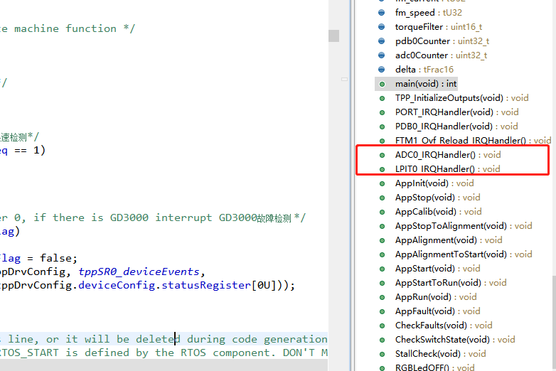
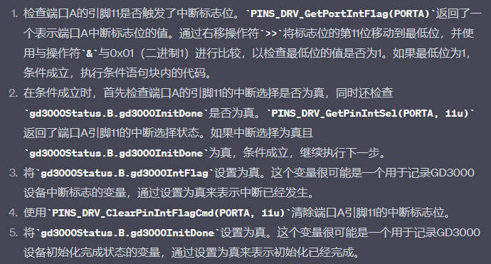
PORT_IRQHandler()
端口中断,主要负责检测GD3000的故障。
if(((PINS_DRV_GetPortIntFlag(PORTA) >> 11u) & 0x01))
	{
		if (PINS_DRV_GetPinIntSel(PORTA, 11u) && gd3000Status.B.gd3000InitDone)
		{
			gd3000Status.B.gd3000IntFlag = true;
		}

		PINS_DRV_ClearPinIntFlagCmd(PORTA, 11u);

		gd3000Status.B.gd3000InitDone = true;
	}
PDB0_IRQHandler()
PDB0中断服务程序,实现计数器++
void PDB0_IRQHandler(void)
{
    pdb0Counter++;

    /* Disable PDB0 */
    PDB_DRV_Disable(INST_PDB0);

    /* Clear PDB0 sequence errors */
    //清除PDB0序列错误
    PDB_DRV_ClearAdcPreTriggerSeqErrFlags(INST_PDB0, 0, 0xFF);

    /* Enable PDB0 */
    PDB_DRV_Enable(INST_PDB0);
}
FTM1_Ovf_Reload_IRQHandler()重点
FTM1功能就是用来测量两次连续换相的时间间隔,以及不同扇区下的PWM设置
void FTM1_Ovf_Reload_IRQHandler()
{
ftm_mod_old = FTM_DRV_GetMod(FTM1);//取FTM1的当前模数值
if(driveStatus.B.Sensorless == 1)//无感模式下
{
if(driveStatus.B.NewZC == 0)//处于两个换相之间的中间状态
{
/* In the middle between two commutations */
//timeZC被设置为actualPeriodZC的一半
timeZC = actualPeriodZC >> 1;
}
/* Update commutation period 更新换相周期*/
FTM1_UPDATE_MOD(actualPeriodZC << 1);
timeZCToff = MLIB_Mul(actualPeriodZC, mcat_cmtTOff);
driveStatus.B.StallCheckReq = 1;//设置驱动状态的StallCheckReq标志位为1
}
else
{
/* Update commutation period */
FTM1_UPDATE_MOD(NextCmtPeriod);
}
ActualCmtSector = NextCmtSector;
if(driveStatus.B.EnableCMT)//在执行换相操作
{
/* Measure back-EMF voltage of the disconnected stator phase flag*/
//设置CommutationFlag标志位为TRUE,用于测量已断开的定子相的反电动势电压
CommutationFlag = TRUE;
NextCmtSector++;
if(NextCmtSector > 5)//对应6个扇区
{
NextCmtSector = 0;
}
/* Prepare PWM settings for the next commutation sector 准备下一个换相扇区的PWM设置*/
ACTUATE_SetPwmMask(ui8FTM0OutmaskVal[rotationDir][NextCmtSector],
ui16FTM0SwOctrlVal[rotationDir][NextCmtSector], HW_INPUT_TRIG0);
}
driveStatus.B.NewZC = 0;
driveStatus.B.AdcSaved = 0;
driveStatus.B.AfterCMT = 1;
/* Clear FTM1 voer flow Flag 清除FTM1溢出中断标志位*/
FTM1->SC &= ~FTM_SC_TOF_MASK;
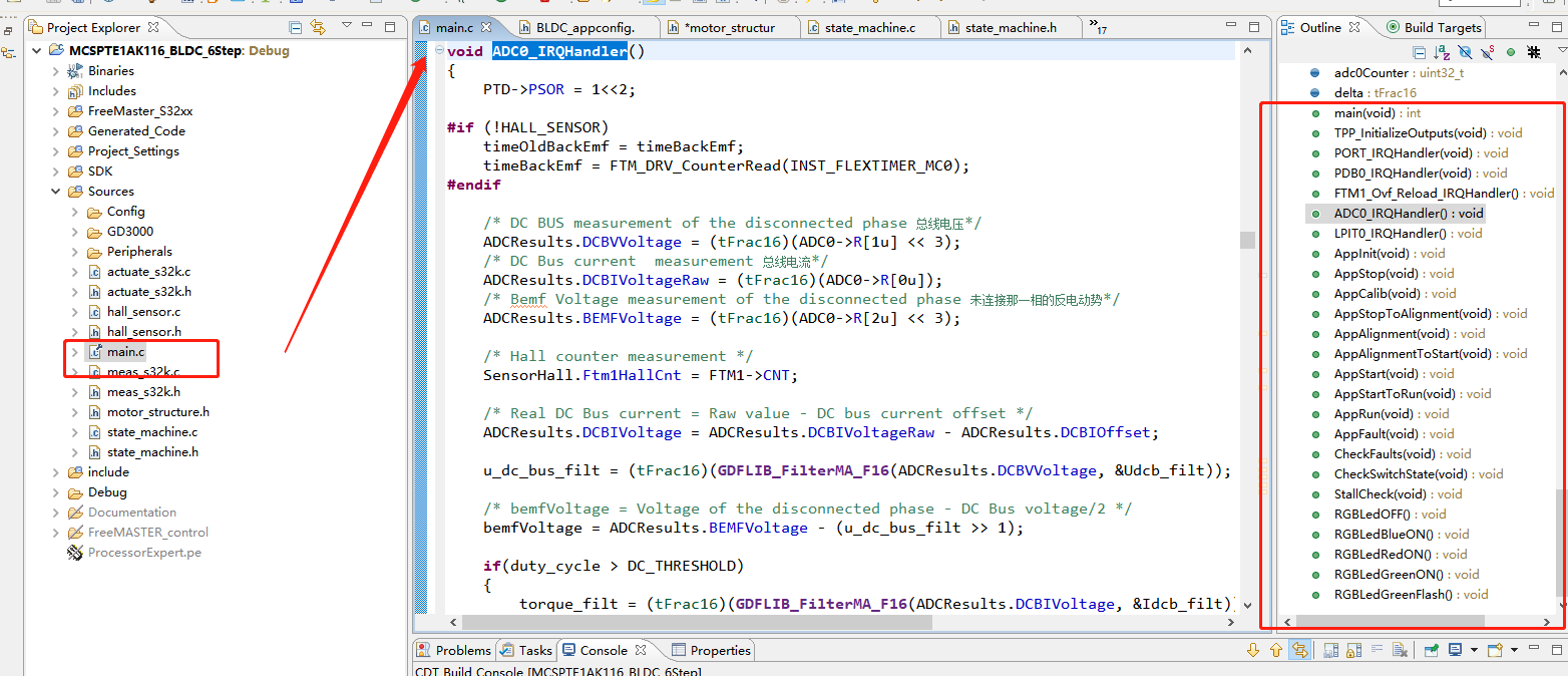
}ADC0_IRQHandler()重点
这段代码的主要作用是处理ADC0的中断事件,执行与电机控制相关的操作,包括测量电压、电流和反电动势,计算换相周期,进行滤波和插值计算等。
void ADC0_IRQHandler()
{
	PTD->PSOR = 1<<2;

#if (!HALL_SENSOR)
    timeOldBackEmf = timeBackEmf;//更新上一次采集反电动势的时间
	timeBackEmf = FTM_DRV_CounterRead(INST_FLEXTIMER_MC0);
#endif

    /* DC BUS measurement of the disconnected phase 总线电压*/
    ADCResults.DCBVVoltage = (tFrac16)(ADC0->R[1u] << 3);
    /* DC Bus current  measurement 总线电流*/
	ADCResults.DCBIVoltageRaw = (tFrac16)(ADC0->R[0u]);
	/* Bemf Voltage measurement of the disconnected phase 未连接那一相的反电动势*/
    ADCResults.BEMFVoltage = (tFrac16)(ADC0->R[2u] << 3);

    /* Hall counter measurement */
    SensorHall.Ftm1HallCnt = FTM1->CNT;

    /* Real DC Bus current = Raw value - DC bus current offset 计算真实的直流母线电流值*/
    ADCResults.DCBIVoltage = ADCResults.DCBIVoltageRaw - ADCResults.DCBIOffset;
    //使用移动平均滤波器(GDFLIB_FilterMA_F16)对直流母线电压进行滤波
    u_dc_bus_filt = (tFrac16)(GDFLIB_FilterMA_F16(ADCResults.DCBVVoltage, &Udcb_filt));

    /* bemfVoltage = Voltage of the disconnected phase - DC Bus voltage/2 */
    //计算公式,计算反电动势电压与1/2总线电压的差值
    bemfVoltage = ADCResults.BEMFVoltage - (u_dc_bus_filt >> 1);

    if(duty_cycle > DC_THRESHOLD)//根据占空比(duty_cycle)的值,决定是否对直流母线电流进行滤波
    {
        torque_filt = (tFrac16)(GDFLIB_FilterMA_F16(ADCResults.DCBIVoltage, &Idcb_filt));
    }
    else
    {
        /* Ignore DC bus current measurement at low duty cycles */
        torque_filt = (tFrac16)(GDFLIB_FilterMA_F16((tFrac16)0, &Idcb_filt));
    }

/* ZC detection algorithm is ignored in Sensorbased mode */
#if (!HALL_SENSOR)
	if(driveStatus.B.AfterCMT == 1)//换相操作后
    {
        if(timeBackEmf > timeZCToff)
        {
            driveStatus.B.AfterCMT = 0;
        }
    }
	//如果不处于换相操作后状态,且也不是新的换相点
    if((driveStatus.B.AfterCMT == 0) && (driveStatus.B.NewZC == 0) && (driveStatus.B.Sensorless == 1))
    {
        /* If the BEMF voltage is falling(0, 2, 4 sector the BEMF voltage is falling), invert BEMF voltage value */
        //如果BEMF电压正在下降,取反bemfVoltage的值
    	if((ActualCmtSector & 0x01) == 0)
        {
            bemfVoltage = -bemfVoltage;
        }

        /* Rising BEMF zero-crossing detection */
    	//如果bemfVoltage大于等于0,表示发生了BEMF电压的上升过零
        if(bemfVoltage >= 0)
        {
            /* Rising interpolation */
            delta = bemfVoltage - bemfVoltageOld;

            /* calculating the time of BEMF zero-crossing */
            if((driveStatus.B.AdcSaved == 1) && (delta > bemfVoltage))
            {
                timeBackEmf -= MLIB_Mul(MLIB_Div(bemfVoltage, delta), (timeBackEmf - timeOldBackEmf));
                //近似插值的那个计算公式,计算过零点
            }
            /* calculating the time just for open loop control */
            else
            {
                timeBackEmf -= ((timeBackEmf - timeOldBackEmf) >> 1);
            }

            lastTimeZC = timeZC;
            timeZC = timeBackEmf;

            /* periodZC = (timeZC - lasTimeZC) + ftm_mod_old(no timer reset) 过零周期*/
            periodZC[ActualCmtSector] = (ftm_mod_old - lastTimeZC) + timeZC;
            /* Average of the previous and current ZC period 求个平均值*/
            actualPeriodZC = (actualPeriodZC + periodZC[ActualCmtSector]) >> 1;
            /* advancedAngle(0.3815) = 0.5 * Advanced Angle(0.763) 计算下一个换相周期*/
            NextCmtPeriod = MLIB_Mul(actualPeriodZC, advanceAngle);

            /* Update commutation period -> FTM1_MOD = timeZC + nextCmtPeriod */
            //更新FTM1的换相周期
            FTM1_UPDATE_MOD(timeZC + NextCmtPeriod);

            driveStatus.B.NewZC = 1;
        }

        bemfVoltageOld = bemfVoltage;   /* Save actual BEMF voltage (for ADC samples interpolation) */

        driveStatus.B.AdcSaved = 1;
    }

    /* S32K11x only one ADC. If changing BEMF phase in FTM1 overflow interrupt, ADC sample will be disorganized and will trigger PDB error */
	if(TRUE == CommutationFlag)
	{
		CommutationFlag = FALSE;
		/* Measure back-EMF voltage of the disconnected stator phase */
		//测量断开相位的反电动势电压
		MEAS_SetBEMFPhase(bemfPhaseList[rotationDir][ActualCmtSector]);
	}

#endif

    /* Timer for Rotor alignment */
	//若处于Alignment状态
	if(driveStatus.B.Alignment)
	{
		if(alignmentTimer > 0)
		{
			alignmentTimer--;
		}
		driveStatus.B.AdcSaved = 0;
	}

	/* Calibration timer for DC bus current offset measurement */
	if(driveStatus.B.Calib)
	{
		calibTimer--;
	}

    /* Application variables record */
    FMSTR_Recorder();

    PTD->PCOR = 1<<2;
}
LPIT0_IRQHandler()重点
处理LPIT0的中断事件,并根据驱动状态执行闭环控制和开环控制的相关操作。其中包括计算电流和转速的PI控制器输出值,更新PWM占空比,设置PDB的延迟时间,以及按键状态的切换CheckSwitchState()
void LPIT0_IRQHandler()
{
uint8_t i;
if(driveStatus.B.CloseLoop == 1)//处于闭环状态下
{
torqueErr = MLIB_SubSat(I_DCB_LIMIT, torque_filt);//计算扭矩误差
//使用PI控制器,计算电流PI控制器的输出值
currentPIOut = GFLIB_ControllerPIpAW_F16(torqueErr, ¤tPIPrms);
/* Speed control */
#if HALL_SENSOR
period6ZC = SensorHall.Period[0];
for(i=1; i<6; i++)
{
period6ZC += SensorHall.Period[i];
}
#else
period6ZC = periodZC[0];
for(i=1; i<6; i++)//六个过零周期
{
period6ZC += periodZC[i];
}
#endif
/* Actual rotor speed is calculated based on ZC period or period measured by FTM1 Moudulus Counter mode */
//计算实际转速
actualSpeed = (uint16_t)(((uint32_t)(SPEED_SCALE_CONST << 15)) / period6ZC);
/* Upper speed limit due to the limited DC bus voltage 12V */
//根据限制的最大DC母线电压(12V)限制所需转速(requiredSpeed)
if(requiredSpeed >= N_NOM)
requiredSpeed = N_NOM;
/* Lower speed limit keeping reliable sensorless operation */
//根据可靠的传感器无感操作保持的最低转速限制(mcat_NMin)限制所需转速
if(requiredSpeed < mcat_NMin)
requiredSpeed = mcat_NMin;
//计算所需转速的斜坡值
requiredSpeedRamp = MLIB_ConvertPU_F16F32(GFLIB_Ramp_F32(MLIB_ConvertPU_F32F16(requiredSpeed), &speedRampPrms));
//计算转速误差
speedErr = requiredSpeedRamp - actualSpeed;
//计算转速PI控制器的输出值
speedPIOut = GFLIB_ControllerPIpAW(speedErr, &speedPIPrms);
//如果电流PI控制器输出值大于等于转速PI控制器输出值,则使用转速PI控制器的输出值
if(currentPIOut >= speedPIOut)
{
/* If max torque not achieved, use speed PI output */
currentPIPrms.f32IntegPartK_1 = MLIB_ConvertPU_F32F16(speedPIOut);
currentPIPrms.f16InK_1 = 0;
/* PWM duty cycle update <- speed PI */
duty_cycle = MLIB_Mul(speedPIOut, PWM_MODULO);
driveStatus.B.CurrentLimiting = 0;
}
else//如果电流PI控制器输出值小于转速PI控制器输出值,则使用电流PI控制器的输出值
{
/* Limit speed PI output by current PI if max. torque achieved */
speedPIPrms.f32IntegPartK_1 = MLIB_ConvertPU_F32F16(currentPIOut);
speedPIPrms.f16InK_1 = 0;
/* PWM duty cycle update <- current PI */
duty_cycle = MLIB_Mul(speedPIOut, PWM_MODULO);
driveStatus.B.CurrentLimiting = 1;
}
/* Update PWM duty cycle 更新PWM的占空比*/
ACTUATE_SetDutycycle((duty_cycle>>1), HW_INPUT_TRIG0);
}
else
{
actualSpeed = 0u;
}
/* Freewheeling is ignored in Sensorbased mode */
#if (!HALL_SENSOR)
if(driveStatus.B.Freewheeling)//如果驱动状态的Freewheeling标志位为1,表示处于自由滑行状态
{
if(freewheelTimer > 0)
{
freewheelTimer--;
}
else
{
driveStatus.B.Freewheeling = 0;
}
}
#endif
/* pdb_delay calculated based on the actual duty_cycle
* to measure DC bus voltage and Back EMF voltage
* towards the end of the active PWM pulse
*/
//根据当前的占空比(duty_cycle)计算PDB(Programmable Delay Block)的延迟时间(pdb_delay1)
pdb_delay1 = (uint16_t)(duty_cycle >> 2);
/* Saturate, if pdb_delay is lower than PDB_DELAY_MIN */
//如果pdb_delay1小于PDB_DELAY_MIN,则将其饱和为PDB_DELAY_MIN
if(pdb_delay1 < PDB_DELAY_MIN)
{
pdb_delay1 = PDB_DELAY_MIN;
}
/* Update PDBs delays 更新PDB的延迟值*/
PDB_DRV_SetAdcPreTriggerDelayValue(INST_PDB0, 0, 1, pdb_delay1);
PDB_DRV_LoadValuesCmd(INST_PDB0);//加载PDB的数值
CheckSwitchState();//调用CheckSwitchState函数,执行状态的切换
LPIT_DRV_ClearInterruptFlagTimerChannels(INST_LPIT1, 0b1);//清除LPIT1的中断标志位
}CheckSwitchState()
该函数的作用是检测用户按键状态,根据开关的按下和释放情况来控制电机的加速、减速、启动和停止操作,并处理故障清除的相关逻辑。函数通过计数器和状态变量来实现消抖和延迟操作。
void CheckSwitchState(void)
{
    if(switchOffCounter == 0)
    {
        /* Speed up or start the motor */
        if(((PINS_DRV_ReadPins(PTD) >> 3) & 1))
        {
            switchCounter[0]++;

            if(switchCounter[0] > SW_PRESS_DEBOUNCE)//SW_PRESS_DEBOUNCE(消抖计数阈值)
            {
                if(appSwitchState == 0)//电机处于未启动状态
                {
                    rotationDir = ROTATION_DIR_CW;//顺时针旋转方向
                    appSwitchState = 1;//表示电机已启动
                    switchOffCounter = SW_PRESS_OFF;//用于延迟开关释放
                }
                else
                {
                    requiredSpeed += SPEED_INC;//如果电机已经启动了,再识别到按键,增加转速
                }

                switchCounter[0] = 0;//清零
            }
        }

        /* Speed down or start the motor 逻辑同上面*/
        if(((PINS_DRV_ReadPins(PTD) >> 5) & 1))
        {
            switchCounter[1]++;

            if(switchCounter[1] > SW_PRESS_DEBOUNCE)
            {
                if(appSwitchState == 0)
                {
                    rotationDir = ROTATION_DIR_CCW;
                    appSwitchState = 1;
                    switchOffCounter = SW_PRESS_OFF;
                }
                else
                {
                    requiredSpeed -= SPEED_DEC;
                }

                switchCounter[1] = 0;
            }
        }

        /* Clear faults or stop the motor 检测是否需要清除故障或停止电机*/
        //如果同时按下减速和加速开关
        if(((PINS_DRV_ReadPins(PTD) >> 5) & 1) && ((PINS_DRV_ReadPins(PTD) >> 3) & 1))
        {
            if(appState == APP_FAULT)
            {
                faultSwitchClear = 1;
            }

            appSwitchState = 0;
            switchOffCounter = SW_PRESS_OFF;
        }
    }
    else
    {
        switchOffCounter--;
    }
}
CheckFaults()
各种故障状态的检测:过流、过压、欠压、堵转、GD3000故障
void CheckFaults(void)
{
    /* DC bus current overcurrent */
    if(ADCResults.DCBIVoltage > I_DCB_OVERCURRENT)//过流
    {
        driveStatus.B.Alignment = 0;
        driveStatus.B.EnableCMT = 0;
        driveStatus.B.CloseLoop = 0;
        driveStatus.B.Sensorless = 0;
        driveStatus.B.NewZC = 0;

        faultStatus.B.OverDCBusCurrent = 1;

        /* Disable actuator */
        ACTUATE_DisableOutput(HW_INPUT_TRIG1);
    }
    else
    {
        faultStatus.B.OverDCBusCurrent = 0;
    }

    /* DC bus voltage overvoltage */
    if(ADCResults.DCBVVoltage > U_DCB_OVERVOLTAGE)//过压
    {
        faultStatus.B.OverDCBusVoltage = 1;

        driveStatus.B.Alignment = 0;
        driveStatus.B.EnableCMT = 0;
        driveStatus.B.CloseLoop = 0;
        driveStatus.B.Sensorless = 0;
        driveStatus.B.NewZC = 0;

        /* Disable actuator */
        ACTUATE_DisableOutput(HW_INPUT_TRIG1);
    }
    else
    {
        faultStatus.B.OverDCBusVoltage = 0;
    }

    /* DC bus voltage undervoltage */
    if(ADCResults.DCBVVoltage < U_DCB_UNDERVOLTAGE)//欠压
    {
        faultStatus.B.UnderDCBusVoltage = 1;

        driveStatus.B.Alignment = 0;
        driveStatus.B.EnableCMT = 0;
        driveStatus.B.CloseLoop = 0;
        driveStatus.B.Sensorless = 0;
        driveStatus.B.NewZC = 0;

        /* Disable actuator */
        ACTUATE_DisableOutput(HW_INPUT_TRIG1);
    }
    else
    {
        faultStatus.B.UnderDCBusVoltage = 0;
    }


    /* MC34GD3000 MOSFET Pre-driver error */
    if (tppDrvConfig.deviceConfig.statusRegister[0U])//GD3000出现故障
    {
        faultStatus.B.PreDriverError = 1;

        driveStatus.B.Alignment = 0;
        driveStatus.B.EnableCMT = 0;
        driveStatus.B.CloseLoop = 0;
        driveStatus.B.Sensorless = 0;
        driveStatus.B.NewZC = 0;

        /* Disable actuator */
        ACTUATE_DisableOutput(HW_INPUT_TRIG1);
    }
    else
    {
        faultStatus.B.PreDriverError = 0;
    }

    /* Stall error */
    if(faultStatus.B.StallError)//堵转
    {
        driveStatus.B.Alignment = 0;
        driveStatus.B.EnableCMT = 0;
        driveStatus.B.CloseLoop = 0;
        driveStatus.B.Sensorless = 0;
        driveStatus.B.NewZC = 0;

        /* Disable actuator */
        ACTUATE_DisableOutput(HW_INPUT_TRIG1);
    }
    //将故障状态寄存器的值(faultStatus.R)写入故障状态寄存器锁存器
    //这样做是为了将故障状态持久化,以便在故障清除后仍能检测到故障。
    faultStatusLatched.R |= faultStatus.R;

    //检查故障状态寄存器锁存器是否不为0。如果故障状态寄存器锁存器不为0,表示发生了故障
    if(faultStatusLatched.R != 0)
    {
        driveStatus.B.Fault = 1;
        appSwitchState = 0;
        appState = APP_FAULT;
    }
    else
    {
        faultSwitchClear = 0;
    }
}
StallCheck()
堵转检测,在无感模式下,评估过零周期的最大和最小值,并根据堵转检测计数器的值判断是否发生了堵转错误。
void StallCheck(void)
{
    /* In Sensorbased mode, StallCheck monitors Hall events */
#if HALL_SENSOR
    if(FTM1->SC & FTM_SC_TOF_MASK)
    {
		driveStatus.B.HallEvent = 0;

		/* Rotor Stall detection in Sensorbased mode based on Hall input */
		if(driveStatus.B.CloseLoop)
		{
			/* Disable FTM1 and Clear timer overflow flag */
			FTM1->SC &= (~FTM_SC_CLKS(1) | (~FTM_SC_TOF_MASK));
			/* Reset FTM1 counter */
			FTM1->CNT = 0;

			/* Rotor Stall Error */
			faultStatus.B.StallError = 1;
		}
    }
#else
    /* In Sensorless mode, StallCheck evaluates ZC period value */
    uint8_t i;
    uint16_t max = 0, min = 65535;

    //将堵转检测请求标志位(driveStatus.B.StallCheckReq)清零
    driveStatus.B.StallCheckReq = 0;

    for(i=0; i<6; i++)//遍历6个过零周期,找到换相周期的最大值(max)和最小值(min)
    {
        if(periodZC[i] > max)
        {
            max = periodZC[i];
        }

        if(periodZC[i] < min)
        {
            min = periodZC[i];
        }
    }

    /* Save min and max commutation periods for tuning purposes */
    //保存最小和最大的过零周期值
    debugTmin = min;
    debugTmax = max;

    periodZcAvrg = period6ZC / 6;//算个平均值

    /* Save min and max commutation periods limits for tuning purposes */
    //保存过零周期的最大和最小限制值
    debugTmaxLim = periodZcAvrg << 1;
    debugTminLim = periodZcAvrg >> 1;

    //如果最大值超过平均值的两倍,或者最小值低于平均值的一半,
    //且堵转检测计数器(stallCheckCounter)未达到最大错误次数(STALLCHECK_MAX_ERRORS),
    //则堵转检测计数器加1。
	if ((max > (periodZcAvrg << 1)) || (min < (periodZcAvrg >> 1)))
	{
		if (stallCheckCounter < STALLCHECK_MAX_ERRORS)
		{
			stallCheckCounter++;
		}
	}
	else
	{
		//如果最小值低于最小过零周期限制值(STALLCHECK_MIN_CMT_PERIOD),
		//且堵转检测计数器未达到最大错误次数(STALLCHECK_MAX_ERRORS),则堵转检测计数器加1
		if (min < STALLCHECK_MIN_CMT_PERIOD)
		{
			if (stallCheckCounter < STALLCHECK_MAX_ERRORS)
			{
				stallCheckCounter++;
			}
		}
		else
		{
			if (stallCheckCounter > 0)
			{
				stallCheckCounter--;
			}
		}
	}

    if (stallCheckCounter >= STALLCHECK_MAX_ERRORS)//堵转检测计数器达到或超过最大错误次数
    {
        faultStatus.B.StallError = 1;//表示发生了转子堵转错误
    }

#endif
}
状态切换函数
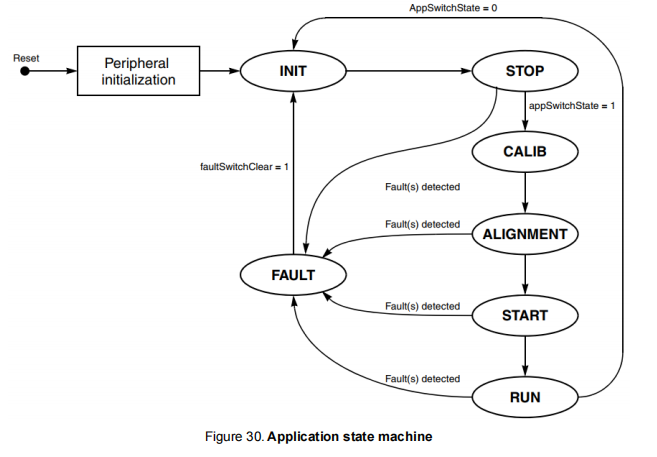

AppInit()
对应状态机INIT状态
void AppInit(void)
{
    uint16_t delay = 10000u;

    driveStatus.B.Alignment = 0;
    driveStatus.B.EnableCMT = 0;
    driveStatus.B.CloseLoop = 0;
    driveStatus.B.Calib = 0;
    driveStatus.B.Sensorless = 0;
    driveStatus.B.NewZC = 0;

    calibTimer 				= CALIB_TIMER;//设置校准定时器的初始值
    /* This is a initial value for Accumulation operation */
    /* Set default current measurement bias offset (actual offset will measured
	   in the Calibration state function) */
	ADCResults.DCBIOffset = FRAC16(0.5);//设置电流测量的偏移量初始值为0.5
	Idcb_calib.f32Acc 		= FRAC16(0.5);

    /* Disable all PWMs */
    ACTUATE_DisableOutput(HW_INPUT_TRIG1);//禁用所有PWM输出

    /* Init parameters for Speed control */
    advanceAngle 			= ADVANCE_ANGLE;//预留角度

    /* Init parameters for SixStep Commutation control 初始化六步换相控制的参数*/
	NextCmtSector = 0;              /* Starting sector */
	NextCmtPeriod = mcat_startCmtPer;
	startCMTcounter = mcat_startCmtCnt - 1;

    /* Wait for DC bus current to settle down (after motor stops) */
	//在电机停止后,等待直流母线电流稳定下来的延迟时间
    while(delay--);

    appState = APP_STOP;//将应用程序状态(appState)设置为APP_STOP,表示初始化时处于停止状态
}
AppStop()
void AppStop(void)
{
#if HALL_SENSOR
    driveStatus.B.StallCheckReq = 1u;
    driveStatus.B.HallEvent = 0u;

    /* Application can be turn on only if rotor stops */
    if((appSwitchState == 1) && (driveStatus.B.HallEvent == 0))
    {
        /* Enable actuator */
        ACTUATE_EnableOutput(HW_INPUT_TRIG1);

        driveStatus.B.Calib = 1;

        appState = APP_CALIB;
    }
#else
    /* Application can be turn on only if rotor stops */
    //检查如果应用程序开关状态为1(表示电机已启动)且驱动状态的Freewheeling标志位为0(表示不处于自由滑行状态)
    if((appSwitchState == 1) && (driveStatus.B.Freewheeling == 0))
    {
        /* Enable actuator */
        ACTUATE_EnableOutput(HW_INPUT_TRIG1);

        driveStatus.B.Calib = 1;//设置驱动状态的Calib标志位为1,表示需要进行校准

        appState = APP_CALIB;//设置应用程序状态为APP_CALIB,表示进入校准状态
    }
#endif
}
AppCalib()
直流总线电流校准

void AppCalib(void)
{
    /* Measure DC bus current offset 直流总线电流校准*/
	ADCResults.DCBIOffset = GDFLIB_FilterMA_F16(ADCResults.DCBIVoltageRaw, &Idcb_calib);

	if(calibTimer == 0)//校准时间为零后
	{
		AppStopToAlignment();//进入预定位
	}
}
AppStopToAlignment()
void AppStopToAlignment(void)
{
    driveStatus.B.Alignment = 1;
    driveStatus.B.EnableCMT = 0;
    driveStatus.B.CloseLoop = 0;
    driveStatus.B.Calib = 0;
    driveStatus.B.Sensorless = 0;
    driveStatus.B.NewZC = 0;

    alignmentTimer = mcat_alignDuration;
    duty_cycle = MLIB_Mul(PWM_MODULO, mcat_alignVoltage);

    /* Update PWM duty cycle 更新PWM的占空比*/
    ACTUATE_SetDutycycle((duty_cycle>>1), HW_INPUT_TRIG1);
    /* Apply PWM settings for motor alignment 给PWM下指令开始预定位*/
    ACTUATE_SetPwmMask(ui8FTM0OutmaskVal[0][6], ui16FTM0SwOctrlVal[0][6], HW_INPUT_TRIG1);

    appState = APP_ALIGNMENT;//进入预定位状态
}
AppAlignment()
void AppAlignment(void)
{
    if(alignmentTimer == 0)//等待预定位时间用完
    {
        AppAlignmentToStart();//进入start状态
    }
}
AppAlignmentToStart()
该状态下,属于强制换相,换相周期由STARTUP_CMT_PER控制;电机加速度由START_CMT_ACCELER控制;该状态下的换相次数由STARTUP_CMT_CNT控制。
void AppAlignmentToStart(void)
{
    driveStatus.B.Alignment = 0;
    driveStatus.B.EnableCMT = 1;
    driveStatus.B.AfterCMT  = 0;

#if HALL_SENSOR
    /* Reset FTM1 counter */
	FTM1->CNT = 0;

	/* Start FTM1 counter */
	FTM_DRV_CounterStart(INST_FLEXTIMER_MC0);
#endif
    /* Prepare PWM settings for initial commutation sector */
    ACTUATE_SetPwmMask(ui8FTM0OutmaskVal[rotationDir][NextCmtSector],
                       ui16FTM0SwOctrlVal[rotationDir][NextCmtSector], HW_INPUT_TRIG0);

    /* Open loop startup is ignored in Sensorbased mode */
#if (!HALL_SENSOR)
    /* Stop FTM1 counter 停止FTM1的计数器*/
    /* Force commutation sector 0 PWM settings */
    FTM_DRV_CounterStop(INST_FLEXTIMER_MC0);
    /* Reset FTM1 counter 重置FTM1的计数器(CNT)为0*/
    FTM1->CNT = 0;
    /* Apply STARTUP_CMT_PERIOD to MODULO 将STARTUP_CMT_PERIOD应用于FTM1的MODULO寄存器*/
    FTM_DRV_SetModuloCounterValue(INST_FLEXTIMER_MC0, STARTUP_CMT_PER, true);
    /* Start FTM1 counter 启动FTM1的计数器*/
    FTM_DRV_CounterStart(INST_FLEXTIMER_MC0);

    NextCmtSector++;//下一个换相扇区
    NextCmtPeriod = MLIB_Mul(NextCmtPeriod, mcat_startCmtAcceler);//计算下一个换相周期

    /* Prepare PWM settings for the next commutation sector 准备PWM设置用于下一个换相扇区*/
    ACTUATE_SetPwmMask(ui8FTM0OutmaskVal[rotationDir][NextCmtSector],
                       ui16FTM0SwOctrlVal[rotationDir][NextCmtSector], HW_INPUT_TRIG0);
#endif

    appState = APP_START;
}
AppStart()
void AppStart(void)
{
#if HALL_SENSOR
    AppStartToRun();

    /* Open loop startup is ignored in Sensorbased mode */
#else
    if(driveStatus.B.AfterCMT == 1)//经过换相之后
    {
        timeZC = NextCmtPeriod >> 1;//将timeZC设置为NextCmtPeriod的一半,用于换相时间计算

        startCMTcounter--;
        if(startCMTcounter > 0)//如果startCMTcounter大于0,表示还未完成启动过程
        {
            driveStatus.B.AfterCMT = 0;
            //计算下一个换相周期
            NextCmtPeriod = MLIB_Mul(NextCmtPeriod, mcat_startCmtAcceler);
        }
    }

    if(startCMTcounter == 0)
    {
        AppStartToRun();
    }
#endif
}
AppStartToRun()
void AppStartToRun(void)
{
    uint8_t i = 0u;

    /* Speed PI controller initialization */
    //对速度PI控制器和电流PI控制器进行初始化
    speedPIPrms.f16InK_1 = 0;
    speedPIPrms.f32IntegPartK_1 = (((tFrac32)duty_cycle << 15)/(tFrac32)PWM_MODULO) << 16;

    /* Current PI controller initialization */
    //设置电流PI控制器的初始输入和积分部分与速度PI控制器相同
    currentPIPrms.f16InK_1 = 0;
    currentPIPrms.f32IntegPartK_1 = speedPIPrms.f32IntegPartK_1;

    /* Speed ramp initialization */
    //初始化速度斜坡(speedRampPrms)的状态为最小速度(mcat_NMin)
    speedRampPrms.f32State = MLIB_ConvertPU_F32F16(mcat_NMin);

    appState = APP_RUN;//进入运行状态
    stallCheckCounter = 0;//堵转检测计数器(stallCheckCounter)为0
    faultStatus.B.StallError = 0;//故障状态的StallError标志位清零

    /* Hall/ZC period initialization before entering Close loop mode */
#if HALL_SENSOR
    for(i=0; i<6; i++)
    {
        SensorHall.Period[i] = NextCmtPeriod;
    }
#else
    for(i=0; i<6; i++)
    {
        periodZC[i] = NextCmtPeriod;
    }
    actualPeriodZC = NextCmtPeriod;

    driveStatus.B.Sensorless = 1;
#endif

    /* Start LPIT timer and speed control loop  启动LPIT定时器和速度控制循环*/
    LPIT_DRV_StartTimerChannels(INST_LPIT1, 0x1);

#if HALL_SENSOR
    /* Reset FTM1 counter */
	FTM1->CNT = 0;

	/* Clear FTM1 voer flow Flag */
	FTM1->SC &= ~FTM_SC_TOF_MASK;
#endif

    driveStatus.B.CloseLoop = 1;
}
AppRun()
void AppRun(void)
{
    if(appSwitchState == 0)//按键没被按时
    {
        /* Disable actuator 停止输出控制信号*/
        ACTUATE_DisableOutput(HW_INPUT_TRIG1);

        freewheelTimer = mcat_FreewheelTLong;
        mcat_FreewheelTShort = 0;
        mcat_integThr = 0;
        driveStatus.B.Freewheeling = 1;

        appState = APP_INIT;//进入初始化状态
    }
}
AppFault()
void AppFault(void)
{
    if(faultSwitchClear == 1)
    {
        driveStatus.B.Fault = 0;//将驱动状态的Fault标志位清零,表示故障已解除
        faultStatus.R = 0;
        faultStatusLatched.R = 0;

        /* Clear GD3000 Errors and interrupts */
        tppDrvConfig.deviceConfig.statusRegister[0U] = 0U;
        TPP_ClearInterrupts(&tppDrvConfig, TPP_CLINT0_MASK, TPP_CLINT1_MASK);

        faultSwitchClear = 0;//将故障清除开关(faultSwitchClear)置为0,表示故障清除标志已复位
        appState = APP_INIT;//返回初始化状态
    }
}