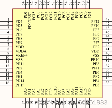
KF32 GPIO
KF32开发
在开发KF32工程时的一些心得,适合新手小白。
GPIO模块的使用
GPIO是通用输入/输出端口的简称,是可控制的引脚,大部分引脚除了当GPIO使用之外,还可以复用位外设功能引脚(比如串口)。

引脚可分为输出模式与输入模式,输出模式通俗理解就是输出高低电平来控制其他硬件,如点灯等,输入模式即为读取其他硬件给他的电平,如键盘输入等。
###初始化
在设计GOIO代码时,需要对GPIO的一些参数进行初始化。
1.输出模式
GPIO_InitTypeDef GPIO_InitStructure;//定义结构体
GPIO_InitStructure.m_Mode = GPIO_MODE_OUT;//配置为GPIO Output模式
GPIO_InitStructure.m_OpenDrain = GPIO_POD_PP;//配置为推挽模式
GPIO_InitStructure.m_PullDown = GPIO_NOPULL;//配置下拉模式为不下拉,配置为GPIO_PULL代表为下拉
GPIO_InitStructure.m_PullUp = GPIO_NOPULL;//配置上拉模式为不上拉,配置为GPIO_PULL代表为上拉
GPIO_InitStructure.m_Speed = GPIO_LOW_SPEED;//配置速度模式为低速
GPIO_InitStructure.m_Pin = GPIO_PIN_MASK_0;//配置需要使用的输出引脚,例:PA0
GPIO_Configuration(GPIOA_SFR, &GPIO_InitStructure);//配置之前设置的配置参数结构体
GPIO_Set_Output_Data_Bits(GPIOA_SFR, GPIO_PIN_MASK_0, Bit_RESET);//配置输出引脚初始电平为低电平,高电平为Bit_SET
初始化结束
程序:
void gpio_init(void)
{
GPIO_InitTypeDef GPIO_InitStructure;
GPIO_InitStructure.m_Mode = GPIO_MODE_OUT;
GPIO_InitStructure.m_OpenDrain = GPIO_POD_PP;
GPIO_InitStructure.m_PullDown = GPIO_NOPULL;
GPIO_InitStructure.m_PullUp = GPIO_NOPULL;
GPIO_InitStructure.m_Speed = GPIO_LOW_SPEED;
GPIO_InitStructure.m_Pin = GPIO_PIN_MASK_0;
GPIO_Configuration(GPIOA_SFR, &GPIO_InitStructure);
GPIO_Set_Output_Data_Bits(GPIOA_SFR, GPIO_PIN_MASK_0, Bit_RESET);
}
2.输入模式
GPIO_InitTypeDef GPIO_InitStructure;//定义结构体
GPIO_InitStructure.m_Mode = GPIO_MODE_IN;//配置为GPIO Input模式
GPIO_InitStructure.m_PullDown = GPIO_NOPULL;//配置下拉模式为不下拉
GPIO_InitStructure.m_PullUp = GPIO_NOPULL;//配置上拉模式为不上拉
GPIO_InitStructure.m_Speed = GPIO_LOW_SPEED;//配置速度模式为低速
GPIO_InitStructure.m_Pin = GPIO_PIN_MASK_0;//配置需要使用的输入引脚,例:PA0
GPIO_Configuration(GPIOA_SFR, &GPIO_InitStructure);//配置之前设置的配置参数结构体
初始化结束
程序:
void gpio_init(void)
{
GPIO_InitTypeDef GPIO_InitStructure;
GPIO_InitStructure.m_Mode = GPIO_MODE_IN;
GPIO_InitStructure.m_PullDown = GPIO_NOPULL;
GPIO_InitStructure.m_PullUp = GPIO_NOPULL;
GPIO_InitStructure.m_Speed = GPIO_LOW_SPEED;
GPIO_InitStructure.m_Pin = GPIO_PIN_MASK_0;
GPIO_Configuration(GPIOA_SFR, &GPIO_InitStructure);
}
注:
输入模式与输出模式的区别为:
输入模式不存在推挽输出,开漏输出设置,没有GPIO_Set_Output_Data_Bits()
推挽输出与开漏输出的区分
详细可参考https://blog.csdn.net/techexchangeischeap/article/details/72569999
个人总结:
推挽输出的最大特点是可以真正能真正的输出高电平和低电平,在两种电平下都具有驱动能力。
开漏输出的一个明显的优势就是可以很方便的调节输出的电平,因为输出电平完全由上拉电阻连接的电源电平决定。另一个好处在于可以实现"线与"功能,所谓的"线与"指的是多个信号线直接连接在一起,只有当所有信号全部为高电平时,合在一起的总线为高电平;只要有任意一个或者多个信号为低电平,则总线为低电平。而推挽输出就不行。用于i2c
###控制电平输出
GPIO_Set_Output_Data_Bits(base, pins, Bit_RESET);//输出低电平
GPIO_Set_Output_Data_Bits(base, pins, Bit_SET);//输出高电平
GPIO_Toggle_Output_Data_Config(base, pins);//电平翻转,适合测试
###控制电平输入
pins_channel_type_t pin_in_temp;
pin_in_temp = GPIO_Read_Input_Data_Bit(base, pins);//读取电平
over