HDLBits学习(五)Circuits--Sequential Logic(时序逻辑)-Latched and Fli-Flops
Latches and Flip-Flops(触发器和锁存器)
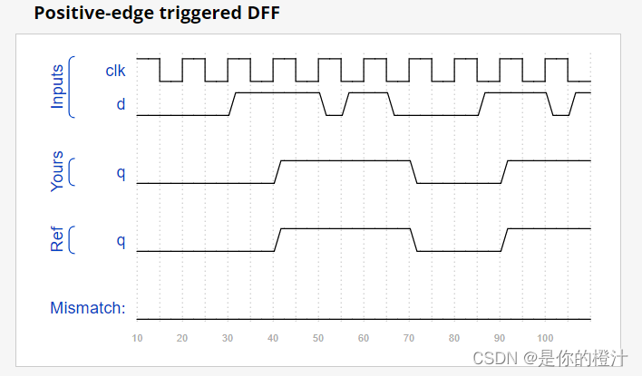
Dff——D触发器
D Latch
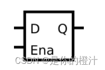
从做题的角度来说,首先你得认识这个元件。同 D触发器相比,这个元件没有 clk 端口,取而代之的是 ena 端口,所以这是一个锁存器。锁存器的特征在于,相较于 D触发器的触发事件发生于 clk 时钟的边沿,锁存器锁存的触发事件发生于使能端 ena 的电平。
当你成功实现了这个锁存器时,Quartus 会提醒(祝贺)你生成了一个锁存器。锁存器相比触发器会消耗更多的资源,所以综合器会在推断出锁存器时产生提醒,防止开发者在不想使用锁存器时,因为代码风格等原因误产生了锁存器。
always@(*)begin
if(ena)begin
q<=d;
end
end
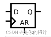
上图为带有异步复位AR端口的D触发器 asynchronous reset
code:
module top_module (
input clk,
input d,
input ar, // asynchronous reset
output q);
always@(posedge clk or posedge ar)begin
if(ar)begin
q <= 1'b0;
end else begin
q <= d;
end
end
endmodule
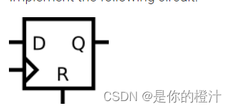
同步复位
always @(posedge clk)begin
if(r)begin
q <= 0;
end else begin
q <= d;
end
end
Mux abd DFF1
假设你想为这个电路实现分层的Verilog代码,使用其中有触发器和多路复用器的子模块的三个实例。为这个子模块编写一个名为top_module的Verilog模块(包含一个触发器和多路器)。
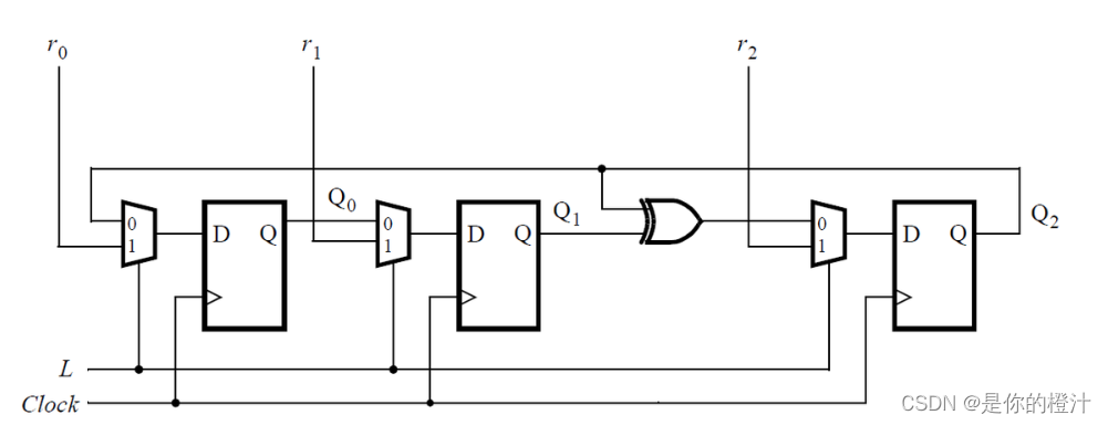
module top_module (
input clk,
input L,
input r_in,
input q_in,
output reg Q);
wire in ;
assign in=(L)?r_in:q_in;
always @(posedge clk)begin
Q <= in;
end
endmodule
Mux and DFF2
考虑如下所示的n位移位寄存器电路:为该电路的一级编写一个名为top_module的Verilog模块,包括触发器和多路复用器。
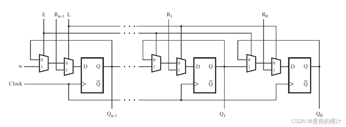
module top_module (
input clk,
input w, R, E, L,
output Q
);
wire in1;
wire in2;
assign in1=E?w:Q;
assign in2=L?R:in1;
always @(posedge clk)begin
Q <= in2;
endendmodule
DFFs and gates
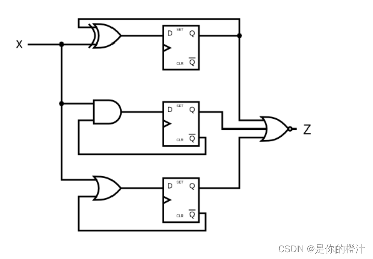
module top_module (
input clk,
input x,
output z
);
wire gate1,gate2,gate3;
reg Q1,Q2,Q3;
assign gate1= x^Q1;
assign gate2=x&~Q2;
assign gate3=x|~Q3;
always @(posedge clk)begin
Q1 <= gate1;
Q2 <= gate2;
Q3 <= gate3;
end
assign z=~(Q1|Q2|Q3);
endmodule
一种真值表的实现方式:
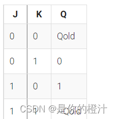
module top_module (
input clk,
input j,
input k,
output Q);always @ (posedge clk)
begin
case ({j, k})
2'b00: Q <= Q;
2'b01: Q <= 1'b0;
2'b10: Q <= 1'b1;
2'b11: Q <= ~Q;
endcase
endendmodule
Delect an edge*******
对于每个8bit的变量,检测这些信号什么时候从0变为1(类似检测上升沿),输出应该在0到1 变化之后才有值。
下图给我们展示了输入in[1]和输出pedge[1]的时序关系图:

module top_module (
input clk,
input [7:0] in,
output [7:0] pedge
);
//上升沿检测
reg [7:0]t;
always @(posedge clk)begin
t <= in;
pedge <= ~t & in;
end
endmodule
Detect both edges双边沿检测 xor
module top_module (
input clk,
input [7:0] in,
output [7:0] anyedge
);
reg [7:0]t;
always @(posedge clk)begin
t<=in;
anyedge <= t^in;
endendmodule
Dual-edge triggered flip-flop***独特的思路
我们现在对时钟上升沿与下降沿都已经很熟悉了。但是FPGA没有一个同时检测双边沿的触发器,而且always中的敏感列表也不支持(posedge clk or negedge clk)。
使用MUX的思路:
module top_module (
input clk,
input d,
output q
);
reg t1,t2;
assign q=clk?t1:t2;
always @(posedge clk)begin %记录上升沿的信号
t1 <= d;
end
always @(negedge clk)begin %记录下降沿的信号
t2 <= d;
endendmodule
XOR?
module top_module(
    input clk,
    input d,
    output q);

    reg p, n;

    // clk的上升沿
    always @(posedge clk)
        p <= d ^ n;

    // clk的下降沿
    always @(negedge clk)
        n <= d ^ p;

    //在上升沿时候,p=d^n, 则q=d^n^n=d;
    //在下降沿时候,n=d^p, 则q=p^d^p=d;
    //加载一个新值时会取消旧值。
    assign q = p ^ n;


    // 这样写是无法综合的
    /*always @(posedge clk, negedge clk) begin
        q <= d;
    end*/


endmodule